CineStripScanner - Help
Scanning of 8mm, 9,5 mm and 16mm cine films in short segments( Version 1.9- February 19, 2017 © Wolfgang Kurz, 2016,2017 )
Table of content:
Introduction
CineFilmScanner is a program designed to scan cine films (supported film formats: 8 mm, 9.5 mm and 16 mm) in sections of
2 to 8 inches (5 to 20 cm) with high optical resolution using a standard flatbed scanner in order to extract the film frames
from these strips which than can be used as basis to generate a video.
The photo flatbed scanner must feature an optical resolution of at least 2400 dpi (dots per inch) or even better (4800 dpi)
and it should provide a wide TPU (transparency unit) - the wider, the better.
Special features of the program are:
- Evaluation of the area to be scanned based on the format of the footage and the target video,
- as well as the control of the transport of the cine film through the flatbed scanner (feeding function) exploiting an Arduino board with attached stepper motor shield.
- For 64 bit Twain drivers a strip sharpening function is prepared using USM sharpening
(for 32 bit Twain drivers this is not always possible because the strip images are really large (up to 150 MB). For 32 bit operating systems a maximum of 4 GB main storage is adressable and 2 GB are already occupied by OS functions.
Here the USM function of CineToVidPro or the separate program CineStripSharpener may be used to sharpen the extracted images).
Prerequisites
CineStripScanner is a C# (pronounced "C Scharp") program using the class library of Microsoft .Net 4.6 or
higher as well as the .NET packages SARAFF.TWAIN from Andrei Kirnazhytski (aka Saraff)
and Kaliko Image.Library from Fredrik Schultz.
In addition a TWAIN32 driver or (as far as available) a TWAIN64 driver must be installed for the used flatbed scanner
To use the programm efficiently, it is recommended to exploit a fast processor (preferred a multi core processor) and a
sufficient amount of memory. 4 GB main memory for 32 bit operating systems or even 6 to 8 GB for 64 bit operating systems are
recommended.
As to digitize a cinefilm normally many strips have to be scanned (3600 strips for a 1 hour film if strips contain 24 frames)
a large amount of disk storage is also needed.
Installation and invocation of the Cine Strip Scanner (CineStripScanner)
CineStripScanner is provided as a compressed ZIP File. To install it, it is sufficient to expand the ZIP file
to a directory of your choice. It is recommended to create an installation directory "CineStripScanner" in the
standard program directory for example C:\Programs\CineStripScanner
CineStripScanner requires a library to store the scanned strip files in it. In this library for each digitazation project
a subdirectory must be created with the 4 character project name. In this sudirectory an additional subdirectory named "STRIPS"
must be generated, in which the strip files finally will be stored.
The parameter file "parmINI.txt" is located in the project directory of each scanning project.
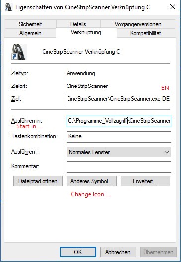
To conveniently invoke the program, you can create a shortcut on the desktop.
In this shortcut you can specify the desired language (EN for English and DE for German (deutsch)).
Additional parameters are the 4 character Project ID and the path to the project base directory.
Implemented are currently (as of November 2016) English and German. Additional languages can be implemented easily
if somebody is capable and willing to do the translation of the text snippets in the application and and store them in a file
located in the instalation directory and called "Const_XX.txt" where XX is the abreviated language identification.
FR French, ES Spanish, PO Portuguese and IT Itlaian are prepared. For other languages a new application compilation has to be requested.
Under "Start in.." in this shortcut the installation directory should be referenced (current librara)e.g.
C:\Programs\CineStripScanner.
Via button "Change icon" you can assign the product logo to this shortcut stored in the installation directory
as shown in the following example (sorry - only available in German):
In the installation directory you also will find a file called "FilmProjDir.txt". It is used to keep the name of the directory selected to hold the files of the film digitization projects.
to the table of content
General Hints
To make best economic use of the available disk storage, the scanned cine film strips should be stored either in the JPG
format (lossy compressed) or in the PNG format (lossless compressed). But PNG normally needs about 10 times more storage
on your hard disk than JPG and the quality increase normally achieved by using PNG does not justify this increased storage requirement.
For the JPG format CineStripScanner allows the definition of a quality factor. Qualityfactor high (100) means good quality
but larger files, qualityfactor low (0) means poor quality but smaller files.
The file names of the scanned strips are composed according to a special sceme.
The file name starts with a 4 character long project name (e.g. "TEST").
The project identification follows a one character
group identification (only digits "0" to "9"). This allows to form 10 strip groups. Finally follows the file name extension,
that is either .jpg or .png.
To avoid later on problems during generation of the video using CineToVidPro exploiting FFMPEG, the first strip
should always start with number XXXXy000.jpg respectively with XXXXy000.png
(XXXX stands for the project id and y stand for the strip group 0 to 9).
The processing steps of the CineStripScanner
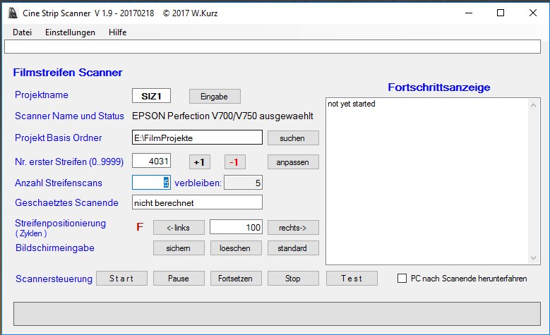
After the invocation of the CineStripScanner the main window is presented. This main window conrols the scanning and the transportation of the cine film and it shows the scanning progress.
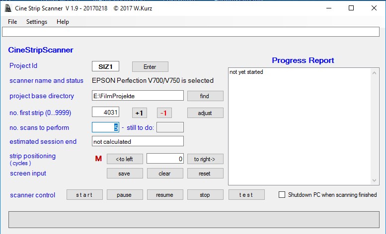
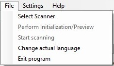
The main window shows in the upper part the menu bar with the menu groups "File", "Settings" and "Help"
and below the message line, in which the scan events and possible errors are presented.
Below the message line in the left part of the window the area to enter the settings for the project parameters
and the parameters to control the scanning loop is located. The most important field is the project name.
After the project name is entered, please press the enter button.
If from a pervious session the film projects directory has been already set, this directory is used again.
If the dierctory has to be changed, than you have to set the new directory path (e.g. by using the "find" button).
The scanner control buttons allow to start, pause, resume and stop a scanning session. The "test" button allows to verify, if the
strip position on the scanner glass is properly set. A test scan is stored in the strip directory but no transport is triggered.
In the right part of the window is the list box showing the scanning progress.
Field strip positioning allows to move the strip a certain number of cycles (a cycle = 4 fullsteps or 8 microsteps) to the left
or to the right.
In the lower part of the windows the buttons to control the scanning loop and one line below the last scanned strip is shown in which
two vertical red lines mark the area of the usable images.
In addition you can define here that the computer should be shut down after completion af all scans.
Setting of the presentation language
If the main window is not presented in the correct language (because the language parameter has not be set in the invocation command), the desired language can be set via menu option "File -> change actual language"
In this window you can select the desired language from the list of available languages. When the button "return" is clicked, all open windows of the program will be updated to new language.
to the table of contentBefore the scanning of the film strips can be started, the required parameters for the scanner and the tranportation device must be set. But the scanner and transport settings windows only can be opened, if a project identification is specified an confirmed via the "Enter" button.
Setting of the scanning parameters
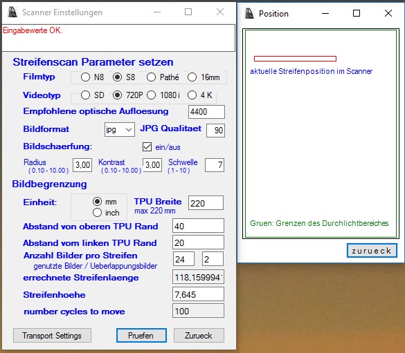
The scanner settings define the strip image format and the desired optical resolution in which the strips shall be stored as well as the position of the scanning area on the scanner window and the dimension (height and length) of this scanning area.
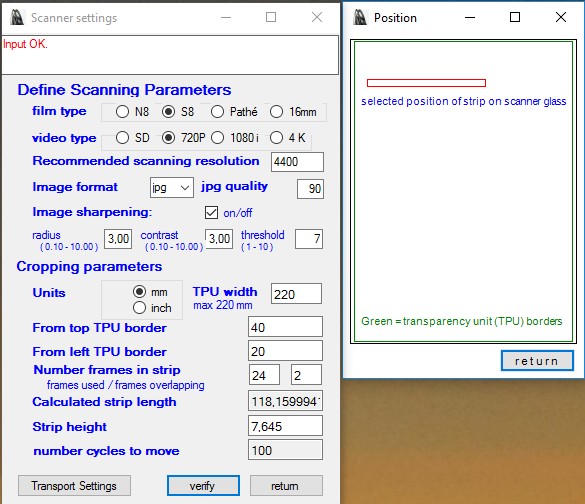
The program recommends the optimal optical resolution of the filmstrips.
This optical resolution is derived from the type of the actual film footage (Normal 8, Super or Single 8, Pathé 9.5 mm or 16 mm)
as well as from the target video type (SD Standard Definition, HD High Definition 720P or 1080i or 4K).
As image format you can selecte from "bmp" (BitMap), "jpg" (Joint Photographic Experts Group)
and "png" (Portable Network Graphics).
JPG and PNG are compressed formats, which means, that certain image information gets lost due to the type of compression applied.
JPG images need relatively little disk storage.
PNG images need up to 10 times more hard disk storage than JPG images.
BMP images provide the full image content, but need therefore a lot of dislk storage.
To define the quality of JPG images
CineStripScanner allows to set a quality factor between 0 (poor quality, relatively low storage requirements) and
100 (best quality, relatively high storage requirements). A recommended quality value is 80% or 90% which creates relatively small files
with still very good image quality.
The scanner settings allow to specify, that after the scanning an USM image sharpening should be performed.
The sharpening is performed like it is done in Photoshop.
You can specify a radius (0.1 to 10 - used for the bluring mask), a contrast value
(0.1 to 10.0 used to increase contrast) and a threshold value (0 to 10 - determining the minimal color difference from which the new pixel color should be applied).
As each scanner is different, you have to experiment a little to find the optimal values. The values radius 5, contrast 3.0 and threshold 7 seem to yield in
good results for most scanners.
Annotation 1: Image sharpening is a time consuming function. For large images (e.g. 24 frames, resolution 4400 dpi) it might very well need some seconds
even with a relatively powerfull machine.
Annotation 2: Image sharpening needs a lot of memory. For large strips with a high resolution it can happen, that you run out of memory
because the TWAIN driver is only available in a 32 Bit version for most currently available consumer scanners. 32 Bits means, that the maximum heap a program can allocate is 2 GB.
If you get an "Out of Memory Exception" you can resolve this problem by one of the following actions:
- scan the strips without sharpening and do the sharpening later with the CineStripSharpener program (recommended).
- use shorter strips.
- reduce the resolution of the strips (e.g. use SD instead of HD).
For the calculation of the strip dimensions and position you first have to set the measurement unit (millimeter (mm)
respectively inches (25.4 mm)).
The following values are then expressed in the selected units of measurement.
Position of the scan area on the scanner pane:
First you have to specify the TPU area width of your scanner. TPU areas can be specified between 50 mm and 220 mm or 2 inches to 8.66 inches wide.
The next value provides the distance of the upper border of the strip to be scanned measuerd from the top border of the
full scanning area (TPU = transparency unit area) of the exploited scanner (but please keep in mind, there is a calibrations area not to be included! It is normally 10 to 15 mm high.).
The following value provides the distance from the left border of the strip to be scanned, measured from the left
border of the scanners full scanning area ( TPU transparency unit area). Caution: if a value is provided, that is to big, then a Twain Parameter Exception may pop up.
If that happens, you must provide a lower value or you must specify a shorter strip length.
For both values you can provide decimal values. As decimal separator you can use either a period or a coma.
Two decimal positions are sufficient.
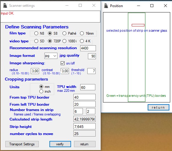
Dimension of the scan area:
The length of the strip to be scanned is calculated from the number of frames to be used from the strip and the number of
overlapping frames at the beginning and the end of each strip.
The height of the scanning area is provided in measurement units (e.g. 0.32 inches (8mm) or 0.64 inches (16mm)).
From the number of frames to be used (according to the definitions in the transport settings) also the number of transport cycles for
the film feeder are calculated.
If all values are provided it must be checked, if the provided values are OK. This is done by clicking button "verify". If the input is OK, a position verification window is shown and the button "return" is enabled. The verified values can be used for scanning.
to the table of contentAfter the scannerdefinitions are provided, also the transport parameters have to be set.
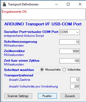
Setting of the transportation parameters
The cine film footage is transported through the scanner stripwise (that means in portions of 2 inches (5 cm)
up to 8 inches (20 cm) - depending on the width of the scanners TPU (transparency unit)) by a feeder device consisting of an
Arduino board and a stepper motor, driven by the Arduino board.
The Arduino board (well suited is an Arduino UNO board) is connected to the computer via a virtual COM Port
which is represented by an USM Port supported by an FTDI driver.
To perform a transport first the transport speed and the transport duration have to be set.
- the transport speed (rotation speed of the stepper motor) is controlled by the delay between 2 consecutive steps performed. The minimal delay (in milliseconds) that can be used (fastest speed) is dependent on the stepper motor used. If using microsteps it can be a little less that if using fullsteps.
- The transport duration is defined by the number of steps to be performed calculated for the strip length.
The provided Arduino script processes for each transport cycle either 4 fullsteps or 8 microsteps.
The transport duration therefore has to be specified in transport cycles. For common 1.8° stepper motors 200 fullsteps
or 400 microsteps result in 1 full revolution of the motor. These are 50 tranport cycles.
How many frames are transported by on revolution is dependent from the sprocketwheel used. Very often wheels with 12 sprockets (taken from old projectors or viewers) are used in manually crafted transport devices.
The transport function of CineStripScanner does not wait, until a transport device signals transport completion.
CineStripScanner starts a new scan after a defined period of time after a transport has been triggered. This allows to overlap
to a certain extent film transportation and scanning to minimize the elapsed time needed for scanning.
A flatbed scanner needs a certain time (most likely about 10 seconds) until the scan bar has reached the scanposition,
from which scanning has to be started. A transport has to be finished at the latest, when this position is reached.
The value "time correction" allows to define, how many milliseconds the starttime of a scan can be reduced in order
to speed up scanning. The absolute transport time is evaluated by multiplying the time needed for 1 cycle
(milliseconds) with the number of cycles requested. From this time period the timme correction is subtracted.
If all values are provided it must be checked, if the provided values are OK. This is done by clicking button "verify". Is the input OK than the button "return" is enabled and the values can be used for scanning.
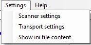
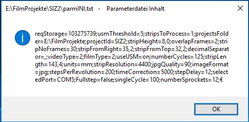
to the table of contentPresetation of the content of the INI File
The parameters controlling the scan process are stored in the parmINI.txt file of the application.
The content of this file can be checked via menu option "Settings -> Show ini file content".
A semicolon in the ini string separates the parameter values.
to the table of content
Start of the strip scanning process
As soon as the scanner settings and the transport settings are specified correctly, the scanning process may be started.
But before triggering the process, you should check again, that all project parameter values are set correctly.
Important is the following:
- The 4 character project name
- The project base directory. If not set, you can set the correct value via the systems standard directory dialog. Click button "find" !
- The strip number of the first strip in the group to be scanned. Group forming is done via the first character in the strip number.
With button "adjust" you can evaluate the currently highest strip number stored in the strip library of the project.
With the buttons " +1 " and " -1 " the number can be modified in single steps. - The number of scans to be performed in the process to be triggered.
Important is, that the position of the film in the scanner is double checked. The film position can be adjusted with the buttons and the field in line strip positioning. With the buttons " <-to left " and " to right-> " the strip can be moved the specified number of cycles into the specified direction. The red character ( "F" or "M" ) visualizes, if fullsteps (F) or microsteps (M)sre used.
In line "screen input" you can "save" or "clear" all input fields of this window
or you can establish the default values by clicking "reset"
In this line you also can specify, that the computer should be shut down after completion of the scanning process.
If all parameters are set and correct, the scan process can be triggered.
To do that, you first have to select the scanner to be used, if several scanners are available
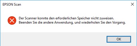
In the list of available scanners the desired scanner must be highlighted and the the button "Select" has to be clicked. You should be sure, that the scanner is propperly connected to the computer and that it is switched on. Otherwies an communication error box is presented. ( See sample in German for an Epson Scanner )

If everything is OK, then the manufacturers graphical user interface (GUI) is presented. With this interface you can do a preview and do one ore several test scans. Strips that are scanned using this GUI are not stored int the projects strip directory "STRIPS".
If you are satisfied with the results than via menu option "File -> Start scanning" or via button
"scanner control -> start" the scan process can be initialized.
You can do an additional test to verify also the position of the strip on the scannerglass by pressing the Test button.
In this case the strip is scanned and stored, but no transport is performed. This allows the repositioning of the strip via the "set Scanner Settings" window.
As long as the strips are scanned consecutively, the scan progress will be reported in the "Progress Report" list box
and the message line shows the file name of the last processd strip.
This strip is also presented as thumbnail image in the control panel at the bottom of the window.
Special functions
Via menu option "Help -> Test for Updates" you can check, if the latest version of CineStripScanner is installed.
und
Via menu option "Help -> About CineStripScanner" the following "About Dialog" is presented.

to the table of content
Last modification: February 19, 2017 WK File: ..../Help_en.html