CineFrameCatcher - Help
CineFrameCatcher Version 2.0 2020-06-21 ---- Copyright © Wolfgang Kurz, 2020
The CineFrameCatcher is a program to support the digitization of cine films in 8 mm, 9,5 mm
(Pathé) and 16
mm format. 9.5 mm and 16 mm formats are currently implemeted but not fully tested, because I have not the ressources to do
that. At that point I want to thank Lawrence Cockell who supported me especially in the area of Pathé and Arduino testing.
The frames of a cine film are caught separately by a video capturing device (digital microscope or similar) and
stored
with consecutive numbers in a frames directory to allow later (in a separate step) to generate a video in SD or HD
format
with a video generation program (e.g. VirtualDub together with AviSynth)
to the table of content
To catch the frames of a cine film you need a special hardware which is unfortunately not available as fully
assembled device that can
be bougth. It must be crafted by yourself, but this is not very difficult if you have a little crafting experiance.
As components to build the device you need:
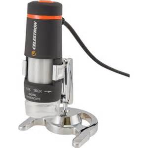
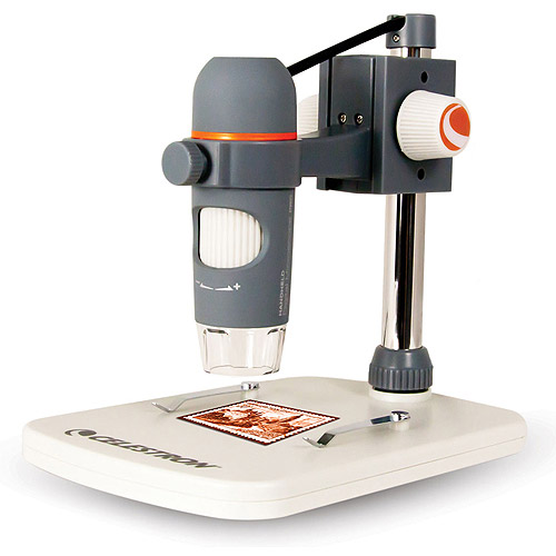
1. A digital microscope.
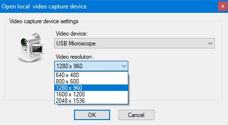
For good quality frames the camera of the microscope should have at least 1.3 Megapixel. This allows a video
resolution of 1280 x 1024 pixel. You can achieve
also a higher resolution when exploiting 5 MP cameras, but this does not necessarily improve the quality of the
final movie.
I use a Celestron Digital Microscope 5 MP (right image), good is also a Celestron Digital Mikroskop 1.3 MP (left
image).
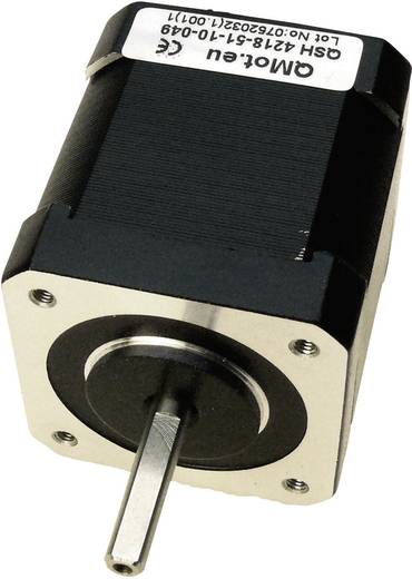
2. A stepper motor to move the film through the transportation unit
Suitable are bipolar 2-phase stepper motors (about 1 to 2 Ampere) with a 1.8° step angle and 200 full steps per
revolution
or (for slightly improved accuracy) 0.9°step angle and 400 full steps per revolution e.g from NanoTech or
Trinamic.
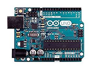
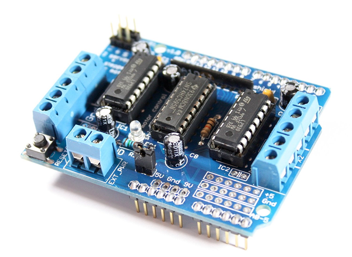
3. A stepper controller
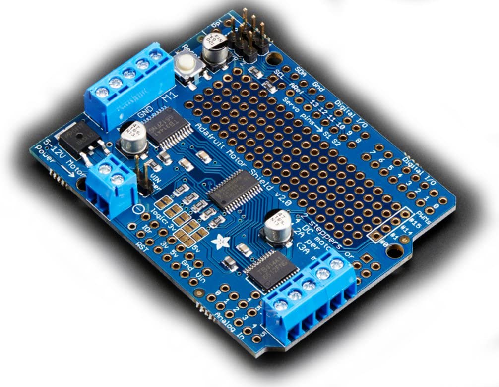
Suitable are controllers driven by an Arduino UNO board (left image) and appropriate motor shield
( e.g. an Arduino motor shield or an Adafruit motor shield) as final output stage (central and right image)
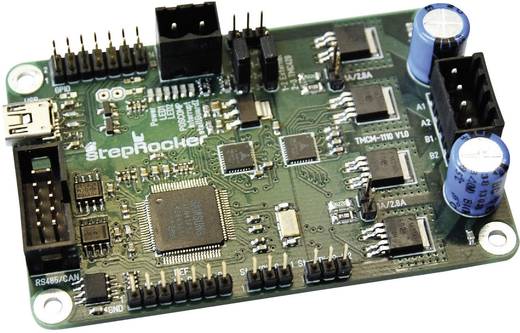
or integrated motor controlers e.g. the Trinamic StepRocker TMCM-1110
(a controller with integrated final output stage - lower image).
Normal 1.8° stepper motors achieve when performing fullsteps an
accuracy of positioning of about 5%.
I therefore recommend a Trinamic StepRocker TMCM-1110. It operates with
microsteps (256 per fullstep) and by that you can
achieve a better positioning accuracy.
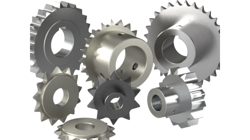
4. A sprocket wheel with 8, 10, 16, 20 or 25 sprockets
The transport of the film must be done frame-wise exploiting a sprocket
wheel for transportation with either 8, 10, 16, 20 or 25 sprockets which fit into the perforation of the film.
(If you use a different number of sprockets you have to code the transportation sketch (script) for your
controller yourself.)
You can get fitting sprocket wheels from old projectors or viewers if you take broken devices appart.
Alternatively you can use a 3D printer to print a plastic sprocket wheel with the desired number of sprockets.
Keep in mind: a smaller number of sprockets is better than a higher number, because you can use a higher number of steps to position the wheel.
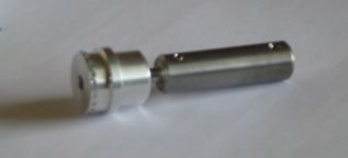
In the internet you can find offerings for files you can use to print the wheel in all desired dimensions. The right image shows examples
of 3D printed wheels. The left image shows a sprocket wheel made from aluminum with an adapted thick axle used to drive the catcher wheel
with a textile enforced rubber belt.
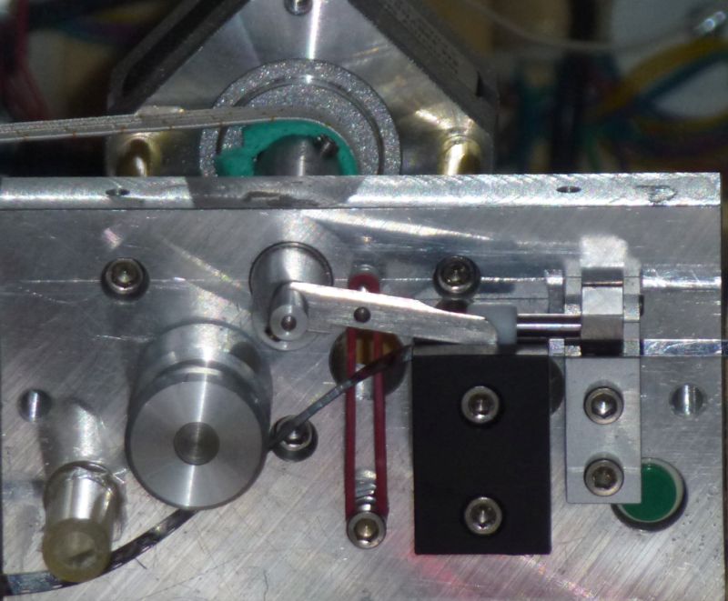
Experienced do-it-yourselfers owning a well equiped workshop may also
create a tranportation grabber according to the
following sample (see image):
(The sketch for this grabber is
from Claus Kappe ! Hint: Rotation clockwise.
The grabber moves a single frame per one full motor revolution by
inserting a little pin into the perforation of the film.
This is a very precise movement. It is comparable to the grabber in the film camera.).
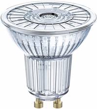
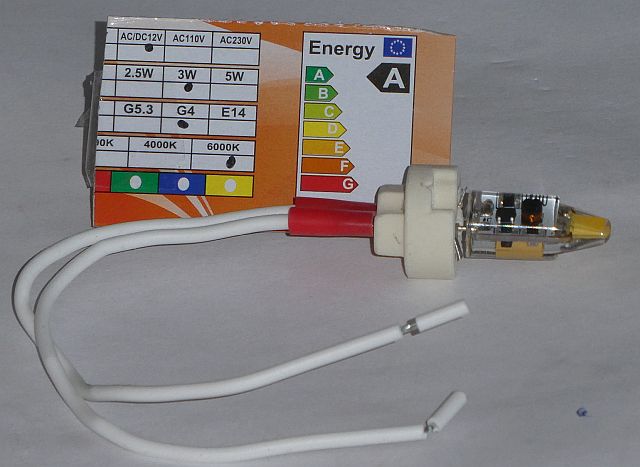
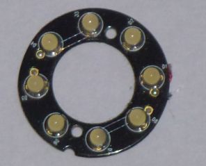
5. A illumination unit.
For the illumination of the transparent film frames you need a light source with a neutral light color (5000°
Kelvin or even higher) - warmer light source - below 5000° Kelvin - causes the scanned images to appear slightly red.
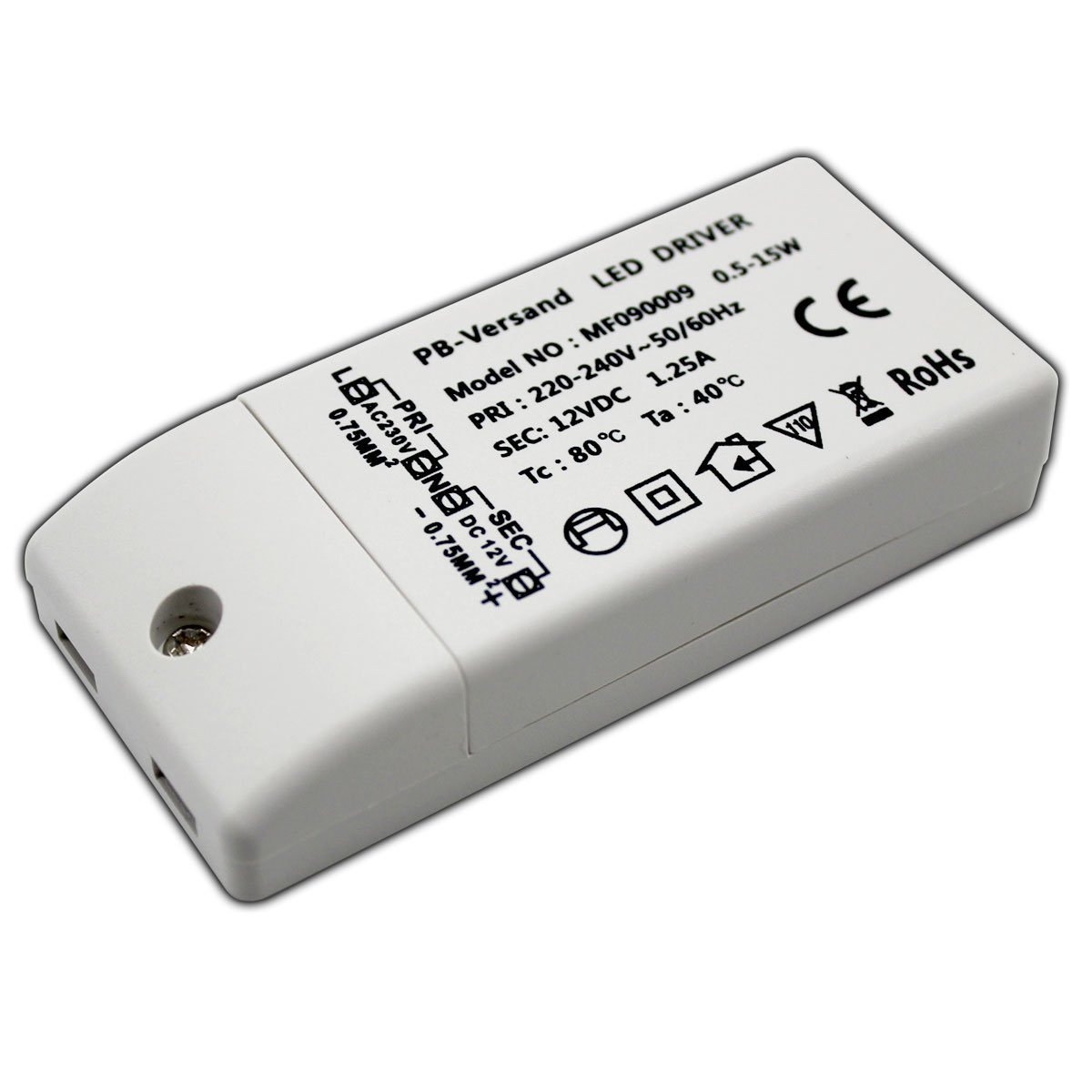
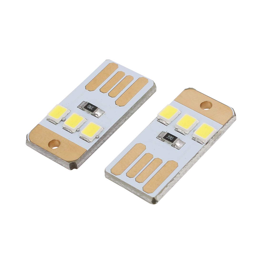
A bulb with 150 to 200 Lumen (2 Watt LED bulb) is normally sufficient. There are several possibilities, e.g. an
OSRAM LED GU10 Reflector 2,6 Watt, DC 12 Volt Light bulbs with Transformer or USB LED bulbs.
You can also exploit the LED ring of the microscope, if it has one. Even a single daylight white LED, if placed correctly, might do.
If the light is too bright, you can use a piece of white cardboard as diffuser to adjust the illumination to the needs of the microiscope used.
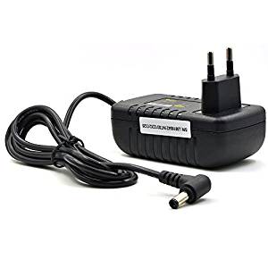
6. A power supply.
To provide the correct power to the unit you need a power supply providing 12 Volt and about 2 Ampere
current.
Suitable are power supplies which are capable also to provide 5 Volts e.g. for the illumination when using little
LEDs
and potentially for running a catching wheel motor. Power supplys of external 3.5" HDDs are a good choice, they are strong enough.
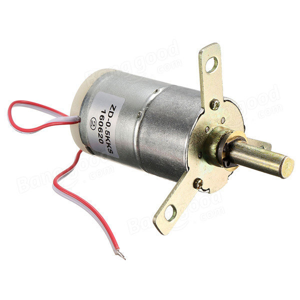
7. A 5 Volt DC (direct current) motor (optional)- probably with a gearbox .
To drive the catching reel you can use a transmission, which is operated by the stepper motor as well
(a textile enforce rubber belt will do. You will find it in the sewing kit of your wife.)
But you can also use an independent 5 Volt DC motor.
The required power on/power off controlling is provided in the attached Arduino sketches,
but it can also be implemented for the StepRocker board.
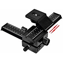
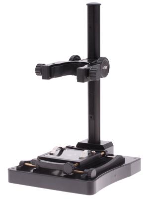
8. A 4 way focusing rail
For an optimal positioning of the microscope over the frame window it
is good practise to use a 4 way focusing rail as it is used in the
macro photograpie as a tripod head or a Microscope stand with
positioning screws (e.g: Conrad Order-No: 191348 - 62 )
A complete transportation unit
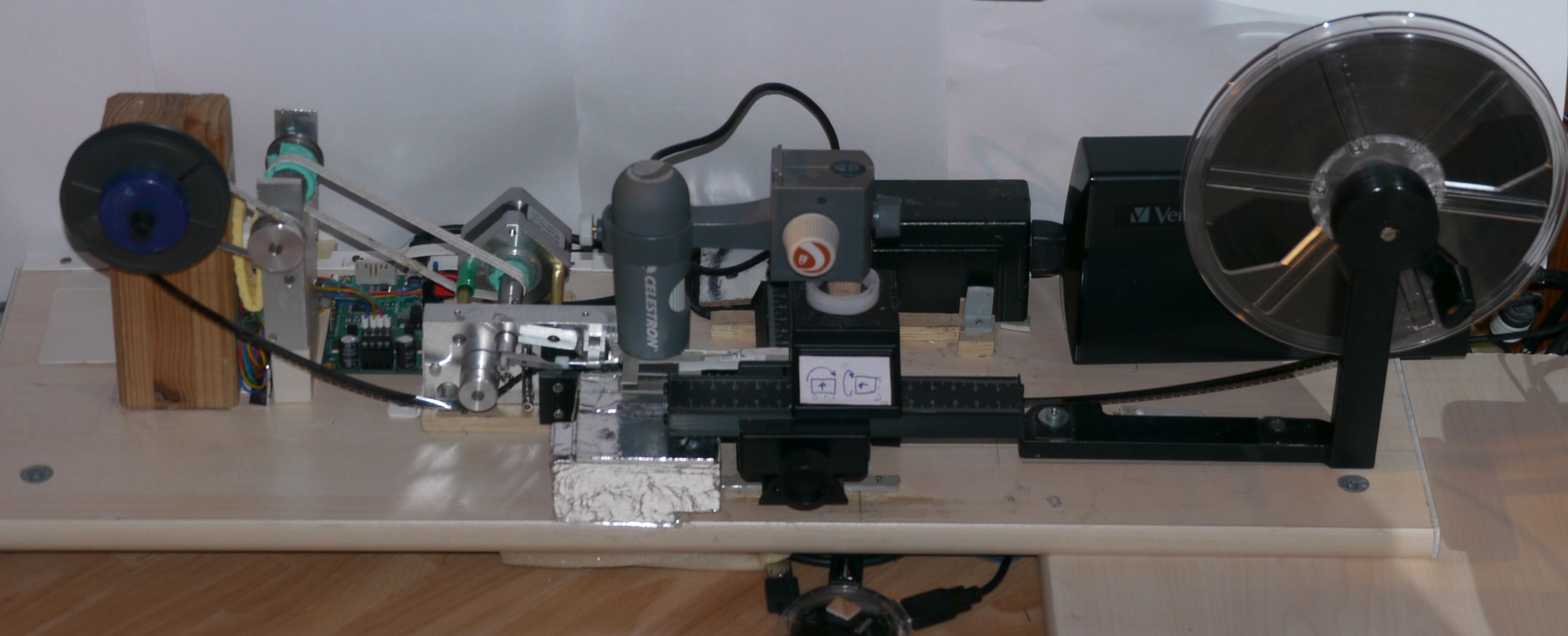
The microscope is placed above the frame window using the 4
way focusing rail. It can be moved precisely in all 3 dimensions with
this device. This allows an exact positioning above the frame window
and a perfect focusing of the lens can be achieved. Good focusing is
very important, because the depth of field is minimal for a focus
length of only several millimeters. You must be able to precisely move
the microscope up and down within a range of 100 to 200 micrometer.
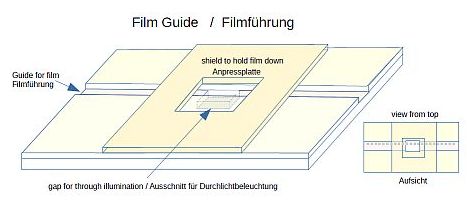
The film is guided below the microscope and above the illumination chamber on a film guidance rail. For the film guide see image below.
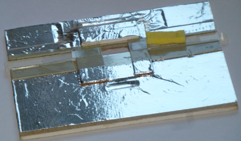
Below the film guidance and the microscope the light chamber is
located. Inside the light chamber there is the illumination unit (light
bulb). Between light bulb and frame window you may have to apply a
diffuser (e.g. a piece of bright white paper - 80 to 160 gr) to achieve
an evenly illuminated area as background for the frame to be grabbed.
Left of the light chamber there is the transportation unit located. It is shown here whit a grabber.
Instead of the grabber you can also use the sprocket wheel which is like the grapper driven by the stepper motor.
Even more to the left you see the capture reel which is driven here
by a transmission. If you like, a 5 Volt DC motor can also be used. It
will be controlled via the StepRocker. The CineFrameCatcher provides
the required electronic signals to the StepRocker.
to the table of content
The CineFrameCatcher is a Windows application developed using MS Visual Studio Community 2019, C# as
programming
language and .NET Framework 4.6.1 as class library (the runtime components of .NET 4.6.1 or better must be installed, to run the
application properly).
The components of the Accord .Net Library 3.8.0 must also be installed (the required components are contained in
the distribution file) and if the Arduino board shall be used, the components of the Solid.Arduino Library (it is
also contained int the distribution file) must be installed as well.
The application can be run on a computer with a MS Windows operating
system (Windows 7 or higher, preferably Windows 10 64 Bit). You can the
application also install under a Virtual Machine (Oracle Virtual Box or
VMWare ...).
The application is delivered via an installation file compressed by 7-Zip. To install the application, it is
sufficient
to unpack the installation file into an installation directory of your choice, e.g. to
C:/Windows/Programs/CineFrameCatcher.
The Windows registry is not used.
For potential updates it is normally sufficient to replace the CineFrameCatcher.EXE file in the installation
directory.
De-Installation is simply done by deleting the installation directory with all it's content.
For the program invocation you can create a desktop shortcut.
Suitable icons to identify the shortcut easily are provided via the
installation file.
Annotation: The application is protected against multiple invocation. It can be executed on a computer only
once. An attempt to run the
application simultaneously a second time will be postponed, until the first invocation has been terminated.
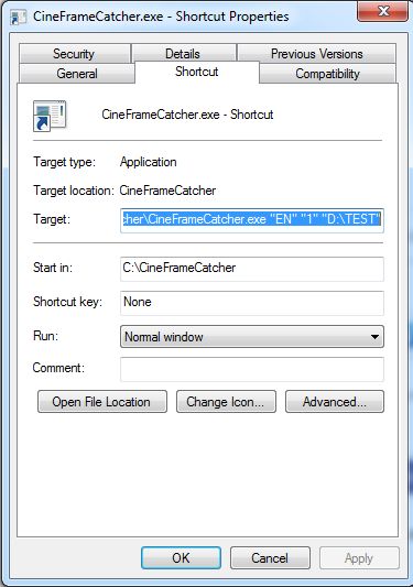
In the desktop shortcut you can provide three invocation parameters:
- A logging control character. "0" = Logging switched off and "1" = Logging switched on.
- the execution languages supported are currently"EN" for English and "DE" for Deutsch (German).
and
- the path to an existing directory (the base directory), into which the application files
(the project directory with their subdirectories "FRAMES" and "VIDEO") are placed which are created for each
project.
To set a new and meaningfull desktop icon in the shortcut, you can use the icons provided in the installation directoy.
to the table of content
The application is started either
- via the EXE file (eventually as described in the example below with the shown invocation parameters)
in the batch command window. Take care about the installation directory!
Example for the batch invocation command C:/Programs/CineFrameCatcher/CineFrameCatcher.exe "EN" "1"
"E:/FilmProjects"
or
- via the desktop shortcut as described above.
As already mentioned, the application can be active only once to prevent images that should be grabbed to be
overwritten.
to the table of content
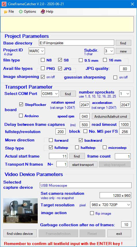
The first window presented is the main window. It provides a menu bar and a message field as well as all required
input fields to control the frame capturing, grouped into 3 categories.
These groups are:
- the Project Parameters
- the Transport Parameters
- the Video Device (Catching) Parameters
The Menu Bar in the Main Window
the menu bar contains three main groups: 1. File,
2. Options and 3. Help
The menu "File" comprises 3 entries.
- Select language
- Create new project
- Exit
The menu "Options" comprises 7 entries.
- Generate AVS File for VirtualDub
- Show actual parameters
- Erase all images in the image subdirectory
- Enable logging
- Disable logging
- Show logfile content
- Clear Logfile content
The menu "Help" comprises 4 entries.
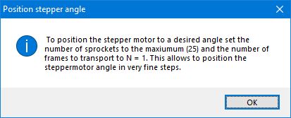
- Stepper positioning
- CineFrameCatcher Help
- Test for updates
- About CineFrameCatcher
File menu items
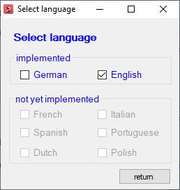
Select language
The presentation language of the application can already be
defined in the invocation parameter. But if - due to special reasons -
a different presentation language should be used, you can via this menu
selection switch to the newly desired language. Currently (as of June
2020) only two languages are implemented Deutsch (DE) and English (EN).
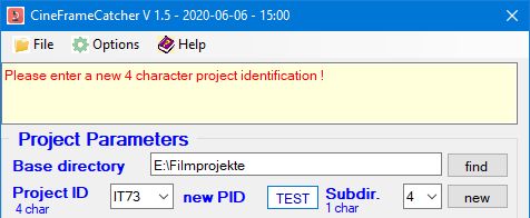
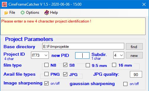
Create new project
If this menu item is clicked, the input fields ( new PID ) needed to create a new project are shown in the "Project
Parameters" section.
You can enter the 4 character idetification of the new project in the new PID field and the required folders are created in the base
directory.
Exit
Via this menu entry the running program will be terminated. All open windows of the application will be closed too
and the actually valid input values are saved in the applications INI file located in the installation folder.
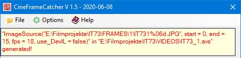
Generate AVS File for VirtualDub
Via this menu item a file is generated with the parameters needed
to generate the video clip exploiting VirtualDub in combination with
AviSynth.
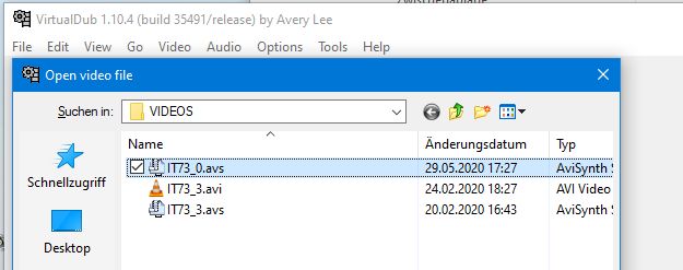
The file with a name composed from the project ID and the actual Frames
subfolder is located in the project's VIDEO folder. It can be used as
video input file in the VirtualDub "File-> Open video file" menu item.
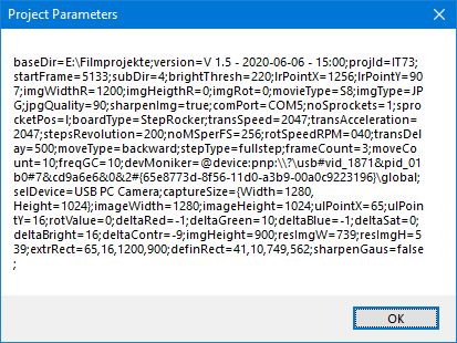
Show actual parameters
This menu entry calls a message box which shows the actual content of the INI file to allow the verification of
these values.
(The constants for the first field initialization are based on the saved values of the preceding session).
If a new project (different from the previous one) is started, you can check, if the values used for initiation
are
correct or if they have to be adjusted.
Erase all images in the image subdirectory
This menu entry causes the deletion of all images in the actually active image subdirectory. The request must be
confirmed via
pressing OK in the upcoming message box. Only the existing files are deleted. Potentially existing
subdirectories will be
kept.
Enable logging
Via this menu item you can enable the logging of application
events if logging is currently not active. This is only possible, if
the logging file is not reserved by a different process, e.g. a text
editor like Notepad or Notepad++
Disable logging
Via this menu you can disable a currently active logging function.
Show logfile content
As a logfile normally contains a lot of entries, this menu entry does not really present the content of the
logfile, It reminds you, that you can view the logfile with a text
editor like Notepad or Notepad++.
Clear logfile content
Via this menu item you should be able to erase the complete content of the active log file.
Options menu items
- Position stepper
This menu item tells you how you can easily position the stepper motor to a desired angle even if it is blocked by a
holding moment. This is especially useful if you use a grabber instead of a sprocket hole.
- CineframeCatcher help
Via this menu entry
the CineFrameCatcher Help file is presented in the web-browser format.
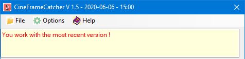
- Test for Updates
Via this menu entry it can be checked if the most recent version
is installed. The computer must be connected to the internet. If a new
version is present in the internet, also during the application start a
message is presented in a message box..
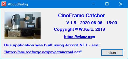
- About CineFrameCatcher
This dialog shows the most important information about the CineFrameCatcher application
to the table of content
The project parameter pane shows all input fields related to and describing the catching project.
Field names and field functions
- Base directory
- The base directory is a global directory into which all
project folders including their subfolders should be located. A project
folder is named by a name with 4 characters e.g. "TEST". A project
folder at least has 2 subfolders. This are the subfolder FRAMES and the
subfolder VIDEOS. The subfolder FRAMES itself has several subfolders
named by a single character e.g. "0", "1", "2", "3", and so on. These FRAMES
subfolders are used to speed up the processing, because folders that
contain more than 10000 files tend to become relatively slow during
processing. As a film easily can comprise 30000 to 50000 images it
makes sense to divide this large number of image files into several
processing groups. The frames of such a processing group are stored in
such a FRAMES subfolder.
- Project-ID
- The 4 character project-id is the name of a digitization project. The 4 characters should provide a
meaningfull abbreviation
for the project. For instance IT73 could be used for "Vacation in Italy 1973". The project name is also
the designation
of the project folder, which is stored as subdirectory in the base directory. The drop-down field shows all
project id's
contained in the base directory.
- New Project-ID
- If via the menu item "File -> Create new project" a new project shall be created, an additional
input
field shows up, into which the new project-id (again only 4 characters) has to be entered. A new
project directory with the entered name is inserted into the base directory and the "FRAMES" and "VIDEO" subdirectories
as well as a subdirectory "0" in the "FRAMES" directory are created for it.
- Subdir (1 char)
- This is a subfolder of the "FRAMES" directory for the frames associated to a certain processing group
of a
project. A new subfolder can be created via button "new". The subfolder is created and selected
immediately. Subfolders are created in numeric and alphabetic order. A subfolder "1" is followed by the subfoler "2",
the subfolder "2" is followed by subfolder "3", the subfolder "9" is followe by subfolder "A" and subfolder "A" is followed
by subfolder "B" and so on.
The drop down list field shows all existing subfolders of a "FRAMES" directory of a certain project.
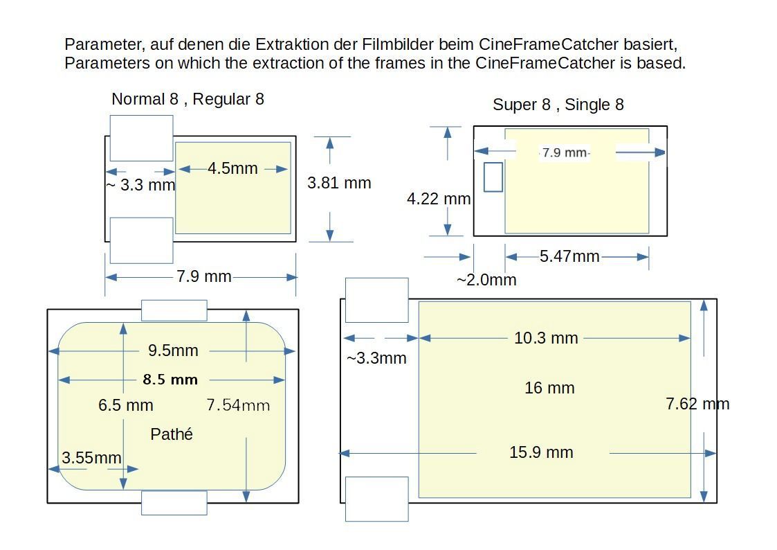
- Film-Type
- The film type determines, how the images of a film must be captured. The following film types can be selected
via the provided
checkmarks:
- Super 8 and Single 8 movies ( S8 )
- Normal 8 or Regular 8 movies ( N8 )
- Pathé [9.5 mm] ( Pathé ) - implementation currently not fully tested due to the lack of the needed footage
- 16 mm movies ( 16mm ) - implemented currently not fully tested due to the lack of the needed footage
This are the parameters used to extract the frames for the various film formats:
- Image-Type
- The grabbed frames of a film may be stored in two different formats. These formats are:
- The JPG or JPEG format (from Joint Photographic Experts Group)
is a format in which images are stored lossy but very compact. JPG
images are according to the compressing strength relatively small -
movie frames in SD or HD resolution need between 30 KB and 100 KB
storage.
- The PNG format (from Portable Network Graphics) is
a format, in which the images are stored lossless but still somehow
compressed. PNG images are about 10 times larger than JPG images but
smaller than uncompressed BMP or TIFF format images (BMP = Bitmap
raster graphic format of Windows, TIFF = taged image file format -
owned by ADOBE).
- JPG-Qual
- The JPG quality reflects the compression strength of a JPG image. The smaller the number, the higher the
compression.
Good compression values, which do not result in poor image
presentation, are 80 to 90. 100 means, the image is not compressed.
- Sharpening parameters
- CineFrameCatcher provides two functions to sharpen the grabbed images, standard image sharpening (left image) and gaussian sharpening (right image).
It is recommended to use the standard image sharpening. Gaussian sharpening very often highlights borders in an image too much,
so that the images show very exaggerated.
Buttons of the project parameter
pane
to the table of content
The transport parameter pane shows all input fields related to and describing the film transportation during
Catching project
performance.
Field name and field function
to the table of content
The video device parameter pane contains the input fields and
buttons to describe the required parameters and actions for the frame
grabbing.
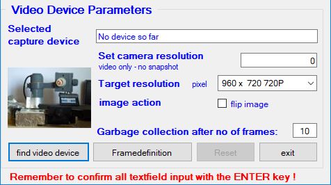
Field names and field functions
to the table of content
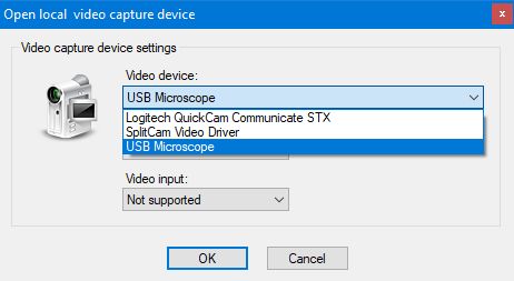
-
The buttons are:
- find video device - already described above. See; find video device and
camera resolution.
You should select the target resolution before pressing this
button, because as soon as the video device and the camera resolution
is set, the video device ist automatically prepared (warmed up) and the
frame definition dialog is started after a certain warming up time. If
the colors of the image still seem not to be fully OK in t he upcoming
frame definition pane, you should press the "c Img. position" button in the window. See
later !
- The button FrameDefinition activates the "Frame Definition Dialog".
- reset - this button resets the form to the default field contents as actually stored in
the INI File..
- exit - by pressing ths button you leave the application, It is the same function as triggerd by
the "File -> Exit" menu.
to the table of content
After the video capture device is started and warmed up, the frame size
and color definition window is presented. It shows the first grabbed
image as seen by the video catching device (the microscope).
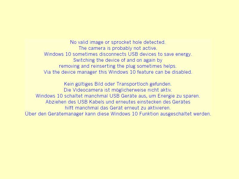
If no image could be scanned (probably because the microscope is not switched on) a notification image
appears that informs you about what might have happened. I also might help to adjust the brightness threshold (default value 220).
This is the color at which the sprocket hole evaluation process decides, which pixels are considered to be bright or dark.
A sprocket hole border is asumed if there is a significant change in the brightness of consecutive pixels.
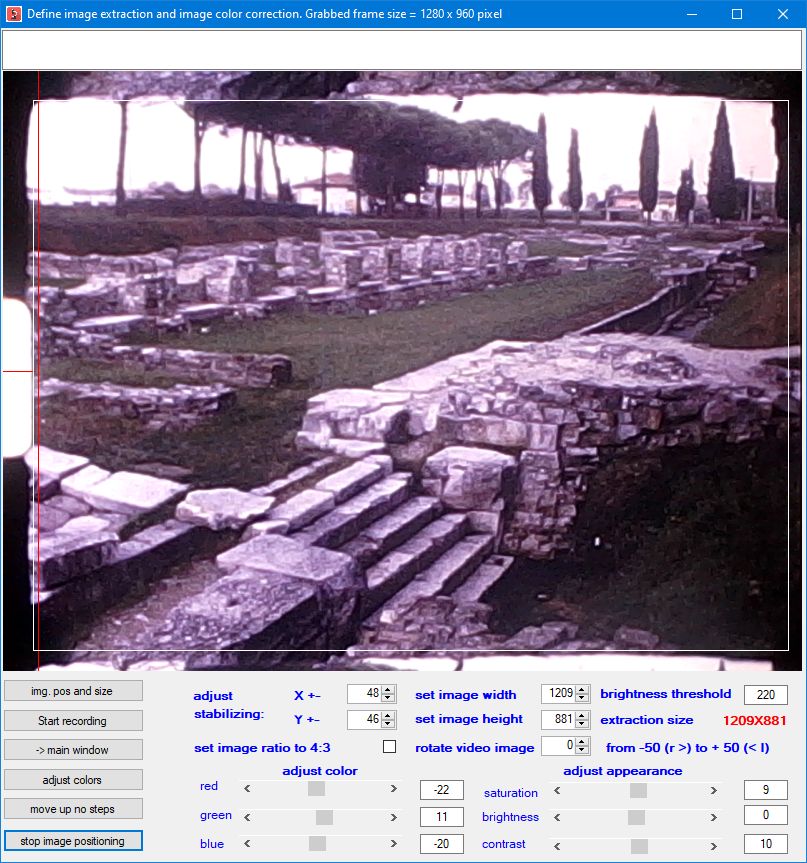
If the image does not fit properly into the window, you have to reposition the grabbed frame in the windows picture
box. This can be achieved by clicking the button "start image positioning" at the left bottom corner in the
Frame Definition Window. If this button is clicked, the window shows the image actually captured by the video capture device.
You now can correct the position by moving it up and down using the 4 way focusing rail.
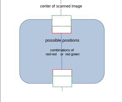
You should position the image in such a way, that for S8 footage at least half the sprocket
hole is visible at the left side of the window. Red lines tell you where the sprocket hole should appear approximately.
If an old extraction definition exists, it is shwon by a white rectangle.
Special care has been taken, if a sprocket wheel is used for transportation and if Pathé footage has to be scanned.
9.5 mm films have the sprocket hole in the middle of the film and not at the left border.
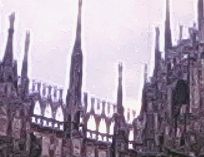
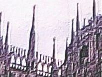
The left image shows the image position,
that should be achieved as start position. The blue area is the definition window rectangle.
Due to the inaccuracy of the stepper motor it might happen, that the scanned images move
up and down. Therefore the magnification should selected in such a way that 2 sprocket holes (or parts thereoff)
allways will be visible .
You may see during scanning positions of the sprocket holes that are a combination of 2 red or a a red and a green hole as shown
in the right image.
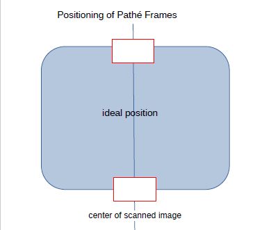
Similar things can happen for film types, where the sprocket holes are located at the left windows side but at the image separation line (16mm or N8 / R8).
If no pre-stabilisation is pssible (no sprocket hole visible or sprocket hole misplaced), it is sufficient to set the
magnification in such a way, that no borders appear in the picture box.
With the microscope you adjust the focusing and the magnification. With the focusing rails you correct the image
position
( up, down., left, right, eventually a rotation). If the result is acceptable, you can terminate the correction
process
and return to the definition dialog by pressing the button "stop image positioning" in the left lower corner of the window.
As we deal with very tiny position changes, this task is not easy.
You have to perform this process very
accurately and it needs significant training to do the job with the required precission.
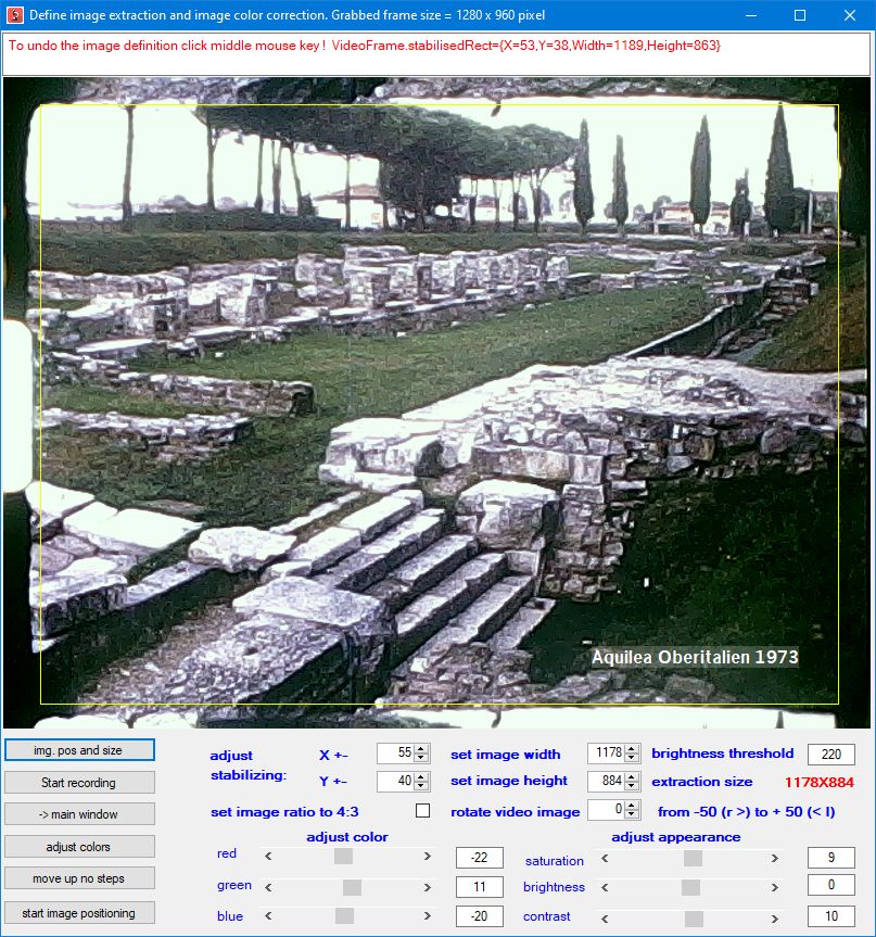
If you'r pleased with the image position, you have to set the extraction size. This is done by clicking the
button "img. pos and size".
You can set the desired section with the left and right mouse button.
First click with the left mouse button in the image at the position, the left upper corner of the final image should be.
Two yellow lines show what has been selected.
Then click with the right mouse button in the image at the position, the right lower corner of the final image should be.
Now a yellow rectangle defines the extraction area.
If yuo are not satisfied with this rectangle, you can repeat the selection by clicking the middle mouse button. The previous
selection will be ignored.
The part of the image which will be caught is now shown in the "Define image extraction and image color correction"
dialog by a yellow rectangle. If the area is not correctly as you want it, you can fine adjust this area via the numeric up and down fields.
6 values can be modified via these fields:
- the X position of the upper left corner of the result image
- the Y position of the upper left corner of the result image
- the desired width of the result image
- the desired height of the result image
- trim image width correction - useful for images which are not stabilized
- the image height correction - useful for images which are not stabilized
The yellow marked image area and the red extraction size text is updated with each change of a value. The window than looks
like this:
The correction values are applied via the fields below the picture box.
With the adjust color and adjust appearance sliders you can correct the colors, brighness, saturation and
the
contrast of the images. To visualize the changes you may click the adjust image button !
The selected values are carried foreward the the extraction process where they are applied to the grabbed images.
With the return button you can go back to the CineFrameCatcher main window.
If the image colors and borders are correctly set, you can start the image catching process by clicking the Start
recording
button. Make sure, that the yellow rectangle is visible when pressing this button.
to the table of content
As soon as the Start Recording button is pressed in the frame definition dialog
With the microscope you adjust the focusing and the magnification. With the focusing rails you correct the image
position
( up, down., left, right, eventually a rotation). If the result is acceptable, you can terminate the correction
process
and return to the definition dialog by pressing the button "stop image positioning" in the left lower corner of the window.
As we deal with very tiny position changes, this task is not easy.
You have to perform this process very
accurately and it needs significant training to do the job with the required precission.
If you'r pleased with the image position, you have to set the extraction size. This is done by clicking the
button "img. pos and size".
You can set the desired section with the left and right mouse button.
First click with the left mouse button in the image at the position, the left upper corner of the final image should be.
Two yellow lines show what has been selected.
Then click with the right mouse button in the image at the position, the right lower corner of the final image should be.
Now a yellow rectangle defines the extraction area.
If yuo are not satisfied with this rectangle, you can repeat the selection by clicking the middle mouse button. The previous
selection will be ignored.
The part of the image which will be caught is now shown in the "Define image extraction and image color correction"
dialog by a yellow rectangle. If the area is not correctly as you want it, you can fine adjust this area via the numeric up and down fields.
6 values can be modified via these fields:
- the X position of the upper left corner of the result image
- the Y position of the upper left corner of the result image
- the desired width of the result image
- the desired height of the result image
- trim image width correction - useful for images which are not stabilized
- the image height correction - useful for images which are not stabilized
The yellow marked image area and the red extraction size text is updated with each change of a value. The window than looks
like this:
The correction values are applied via the fields below the picture box.
With the adjust color and adjust appearance sliders you can correct the colors, brighness, saturation and
the
contrast of the images. To visualize the changes you may click the adjust image button !
The selected values are carried foreward the the extraction process where they are applied to the grabbed images.
With the return button you can go back to the CineFrameCatcher main window.
If the image colors and borders are correctly set, you can start the image catching process by clicking the Start
recording
button. Make sure, that the yellow rectangle is visible when pressing this button.
to the table of content
As soon as the Start Recording button is pressed in the frame definition dialog
the "Image grabbing controller" window opens with the image as grabbed by the microscope as first image.
Pressing the "start" button will start the grabbing process. From this point in time the images are shown in
the progress dialog in their final form as they will be stored in the target folder for video clip generation.(see right picture)
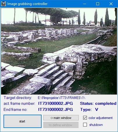
The dialog is invoked from the Start Recording button in the definition dialog.
It shows the the target directory into which the scanned frames are stored.
The second line shows the name of the image actually processed.
The third line shows the name of the last image to be captured, and it indicates, that the frames are retrieved from a video device ("V")
There are 3 buttons.
- The left button has 3 functions:
- start starts the grabbing process at the the beginning of the grabbing session .
- pause interrupts a running grabbing process
- continue continues an interrupted grabbing process.
this button changes its label according to the process state. At the beginning it says START. If you click the button with the START label,
the grabbing process is started and the label is changed to "pause" processing.
When the process is interrupted, you can go to the definition window or the main window to make changes - eg. change the number of images
still to be processd or change the image color.
- The button "-> main window" transfers the control (for the mouse) to the main window and
- the button "to define window" transfers the control (for the mouse) to the definition window
There are 2 check marks.
- The checkmark "color adjustment" triggers color adjustment for the grabbed images according to the settings
in the definition window. If the button is not clicked, no color adjustment is performed.
- The checkmark "shutdown" tell the program, that the computer should be powered off after the grabbing session
has finished. This is usefull for unattended over nicht sessions.
In the main window a progress report is given, which shows, how many frames per minute are grabbed and an
estimate,
when the grabbing session might be completed.
In the message area also sometimes a message shows up, that notifies the observer, that the operating system
has performed a
garbage collection. This is to explain, why sometimes the frame grabbing seems to pause unintetionally.
to the table of content
Last change: June 21, 2020 WK